UNDERSTANDING PRO LINE PROXIMITY PROBE HARDWARE SOLUTIONS
Use these buttons to explore the different proximity probe solutions available for your specific application:
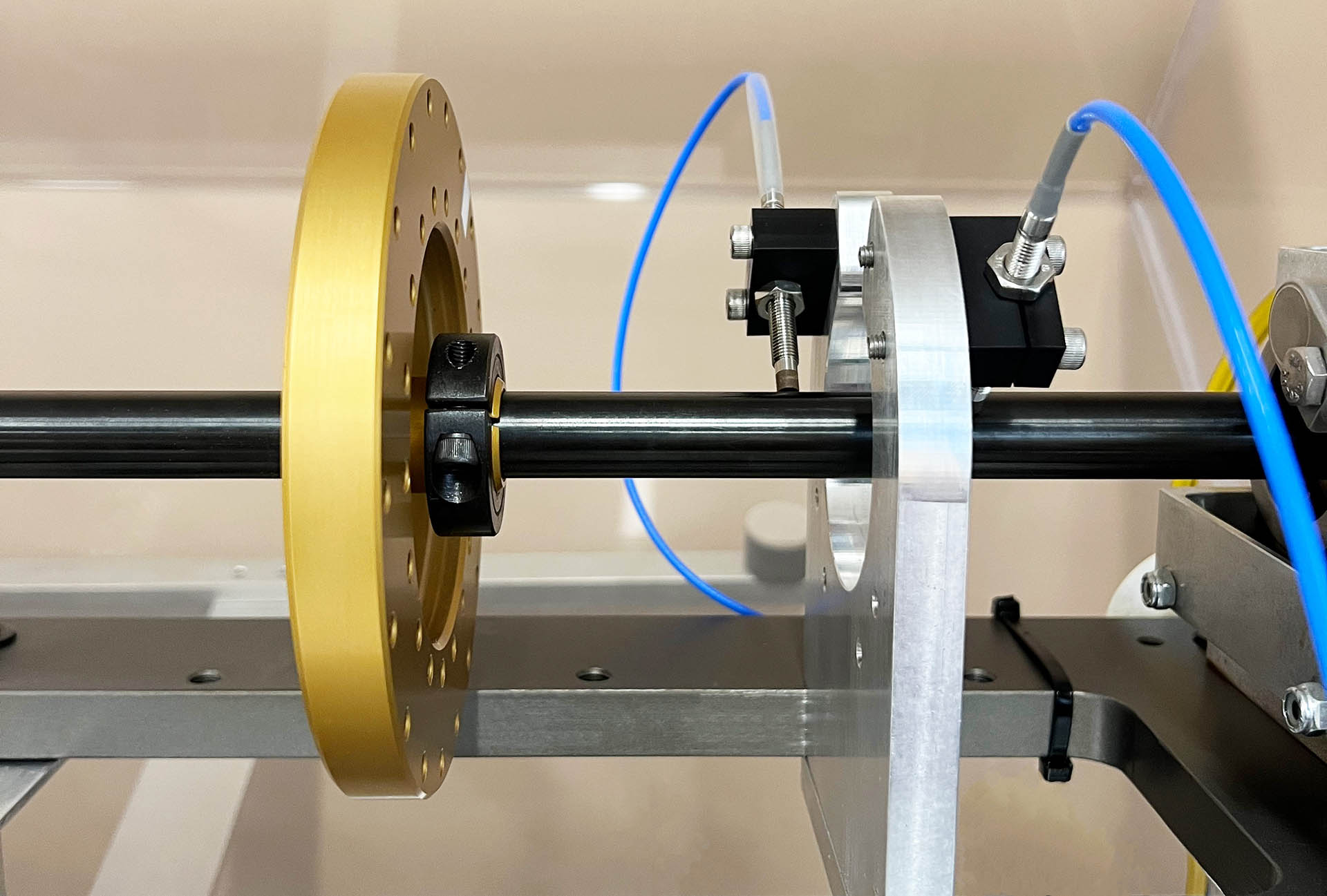
Selecting the Right Proximity Probe Driver for Your Application
CTC offers a wide variety of proximity probe driver configurations. Regardless of configuration, all PRO Line drivers come equipped with a buffered BNC that allows the user access to unfiltered voltage data.
Voltage Drivers
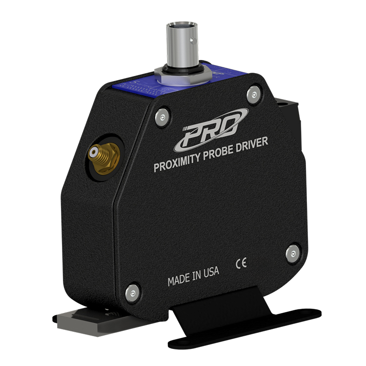
The voltage driver has a dynamic voltage output that is compatible with industry-standard continuous vibration monitoring systems and is the format specified in API Standard 670. The dynamic voltage output is proportional to the DC gap between the target material and the probe tip.
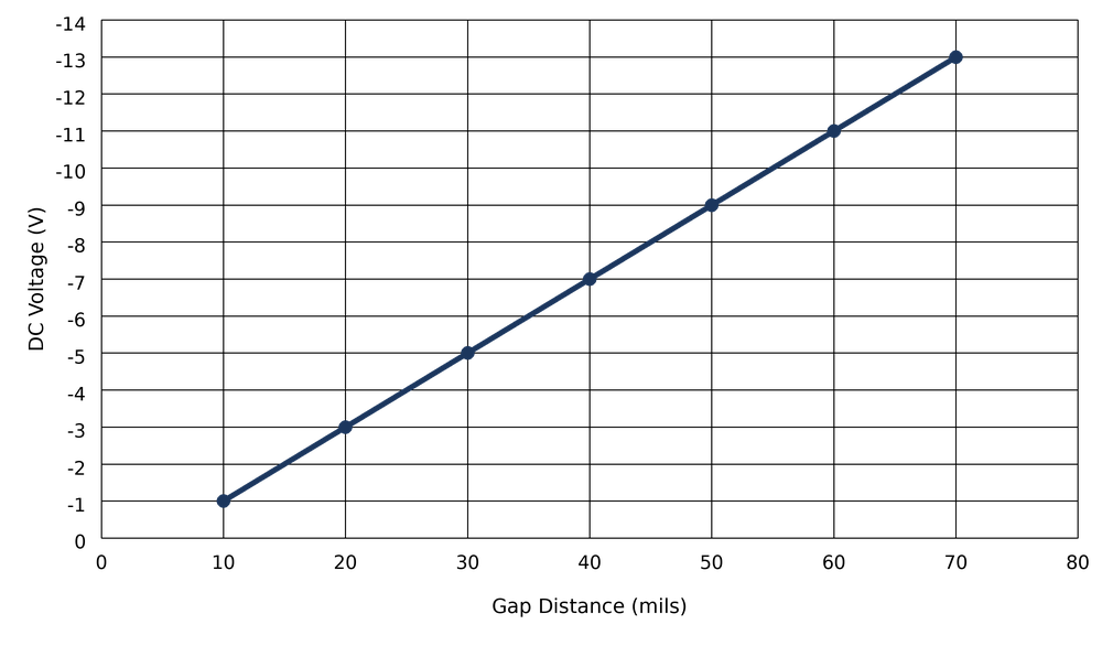
Typical Response Curve - FFv Voltage Driver (10 - 70 mils)
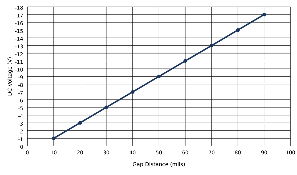
Typical Response Curve - 8 mm Voltage Driver (10 - 90 mils)
Typical Response Curve - 11 mm Voltage Driver (20 - 180 mils)

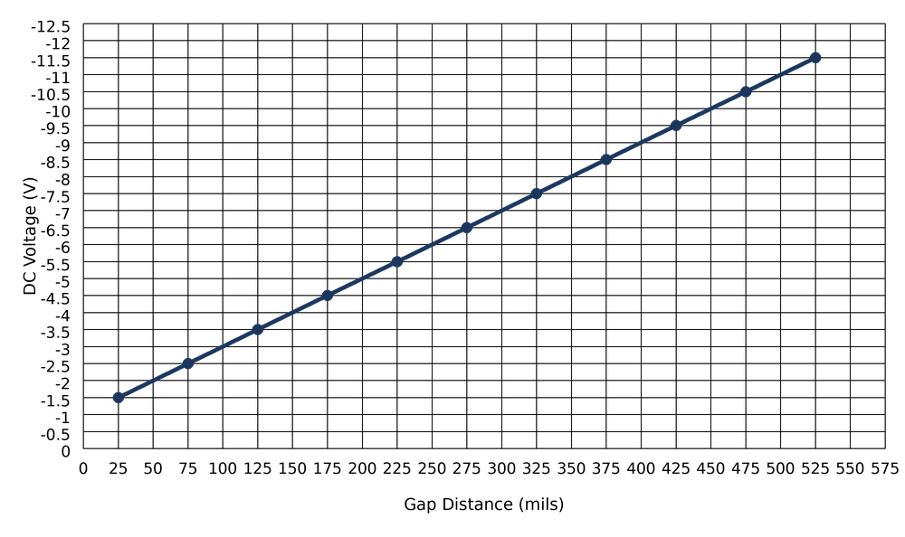
Typical Response Curve - 25 mm Voltage Driver (25 - 525 mils)
4-20 mA Drivers
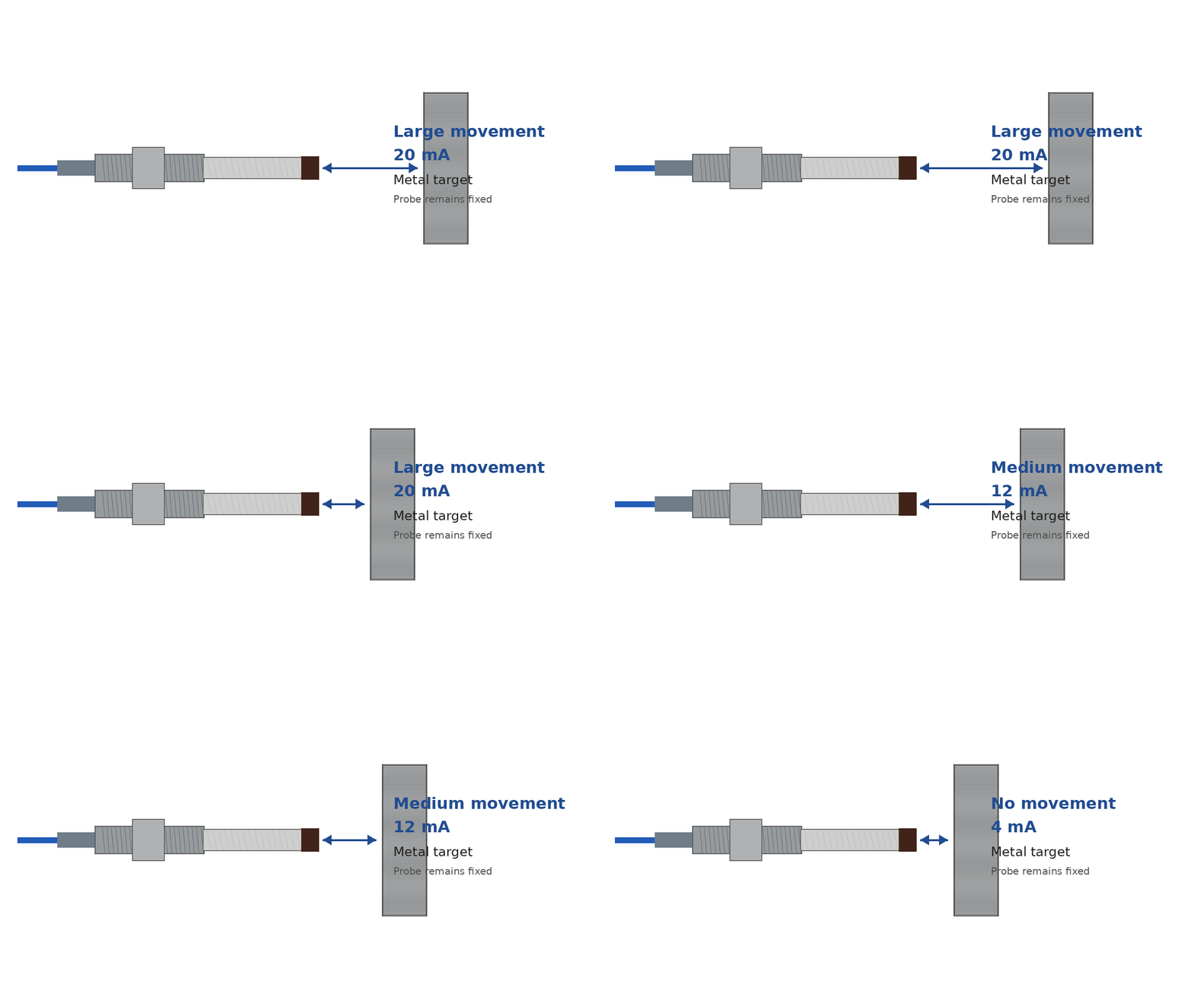
This Current driver option provides a current loop signal, in addition to the voltage output as seen on the voltage drivers, that is proportional to the DC gap distance between the probe tip and the target.
4-20 mA DRIVERS PROPORTIONAL TO DC GAP
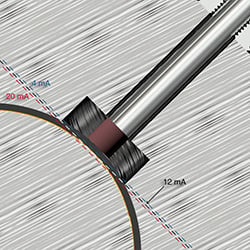
Probe showing proportional output for the 4-20 mA signals.
With shaft surface at 50 mils, 4-20 output is 12 mA.
If the gap increases to 70 mils, 4-20 output will be 16 mA.
Note: Current will be 180° out of phase for 4-20 mA drivers.
The output is linear across the calibrated probe range (e.g., 10 - 90 mils), with 4 mA and 20 mA corresponding to the minimum and maximum limits of that lienar range, respectively. The midpoint of the gap range corresponds to approximately 12 mA.
Typical Response Curve - FFv 4-20 mA Driver (10 - 70 mils)

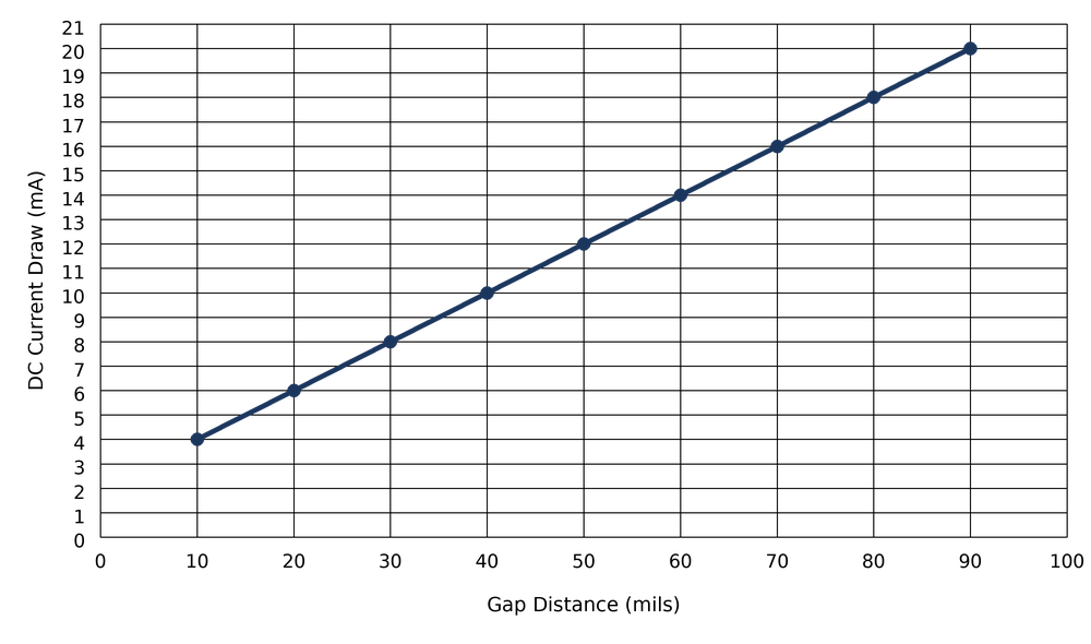
Typical Response Curve - 8 mm 4-20 mA Driver (10 - 90 mils)
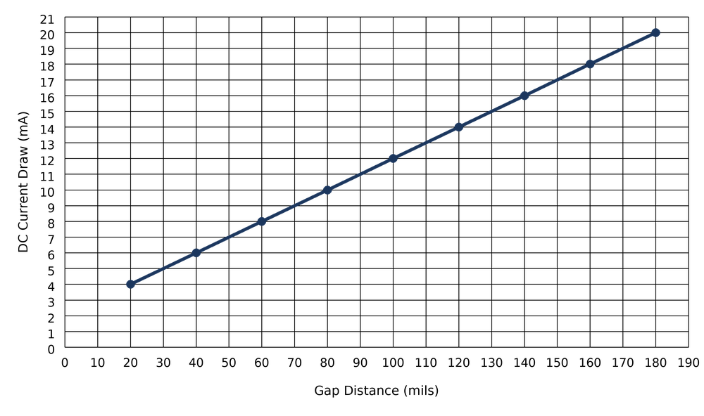
Typical Response Curve - 11 mm 4-20 mA Driver (20 - 180 mils)
Please note, 25 mm 4-20 mA Drivers are not currently offered
RADIAL DRIVERS
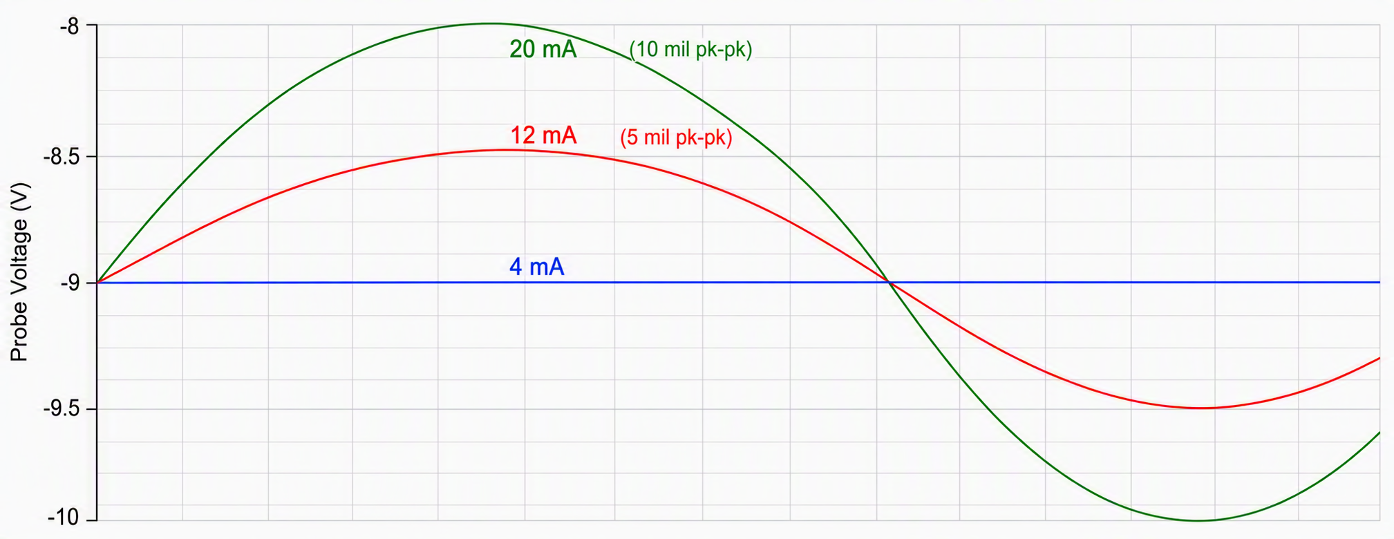
This Current driver option provides a current loop signal, in additional to the voltage output as seen on the voltage drivers, proportional to peak-to-peak shaft displacement (vibration) in mils.
The probe must be set to its midpoint gap (nominal DC voltage, typically ~–9 V), such that the 4–20 mA output represents dynamic motion about this average position.
The "Full Scale Range" specifies the pk–pk displacement corresponding to 20 mA. For example, a 0–5 mil pk–pk unit will output:
- 4 mA at 0 mil pk–pk (no vibration)
- 12 mA at 2.5 mil pk–pk
- 20 mA at ≥5 mil pk–pk
Note: This output is not valid for low-frequency motion (typically below 50 Hz), where dynamic measurement accuracy is reduced.
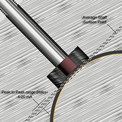
In radial applications, the probe drivers select the average shaft surface distance and the 4-20 is proportional to the overall peak-to-peak vibration in mils around the average surface of the shaft.
Note, phase is not applicable for radial drivers
AXIAL DRIVERS
This Current driver option provides a current loop signal, in addition to the voltage output as seen on the voltage drivers, proportional to axial displacement relative to a defined zero (reference) position.
The midpoint of the output (12 mA) corresponds to the defined zero position (typically near the nominal gap voltage, e.g., ~–9 V). The output then scales linearly with displacement away from this reference:
For a unit specified as "0 ±25 mils":
- 4 mA corresponds to –25 mils (movement toward the probe)
- 12 mA corresponds to 0 mils (reference position)
- 20 mA corresponds to +25 mils (movement away from the probe)
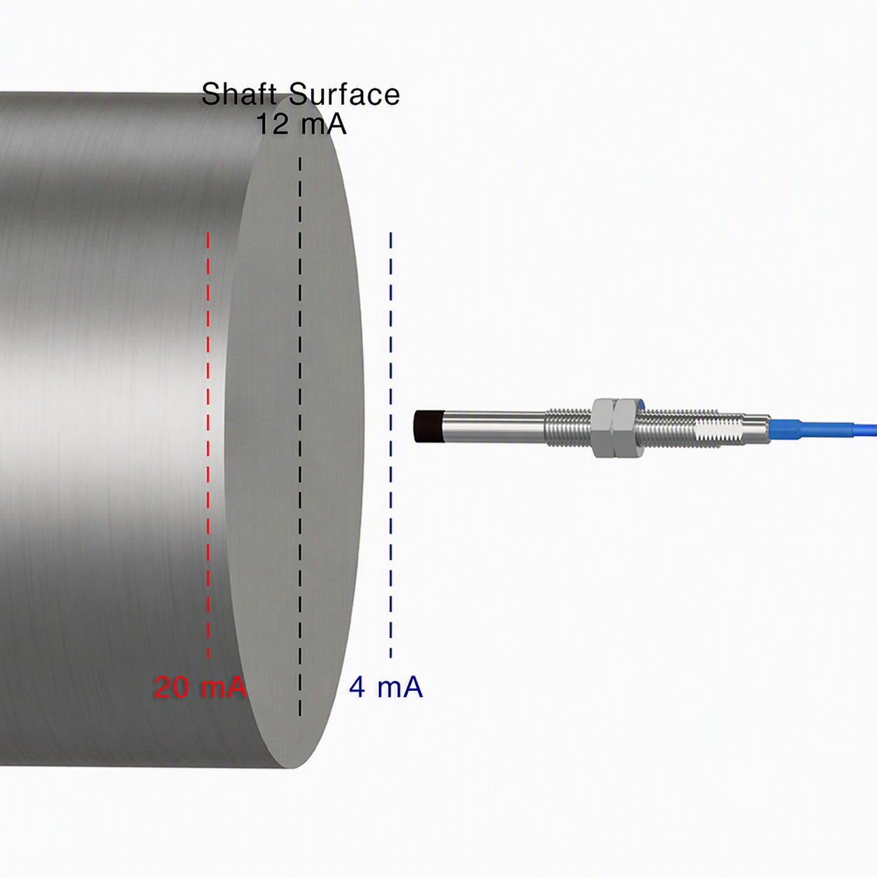
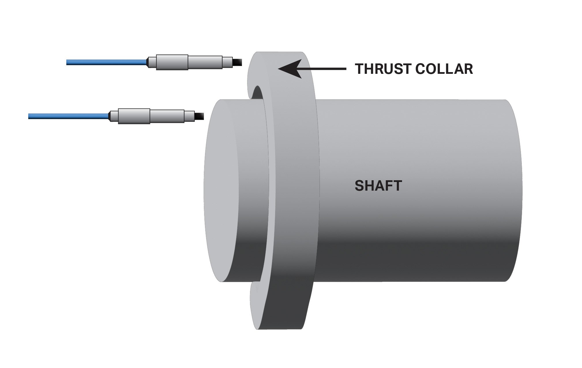
In the thrust position the probes auto-range to the face of the shaft or thrust collar and the 4-20 is proportional to the positive or negative vibration away or toward the probe, as shown.
Note, current will be 90 degrees out of phase for axial driver.
Typical Response Curve - FFv Axial Driver (5 - 75 mils)

Typical Response Curve - 8 mm Axial Driver (5 - 90 mils)
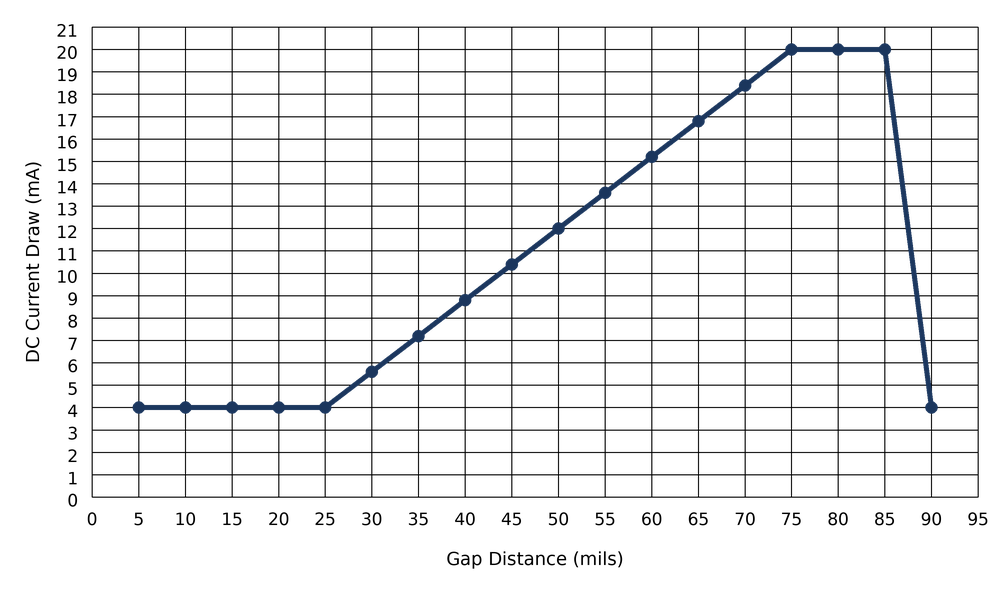
Typical Response Curve - 11 mm Axial Driver (20 - 180 mils)
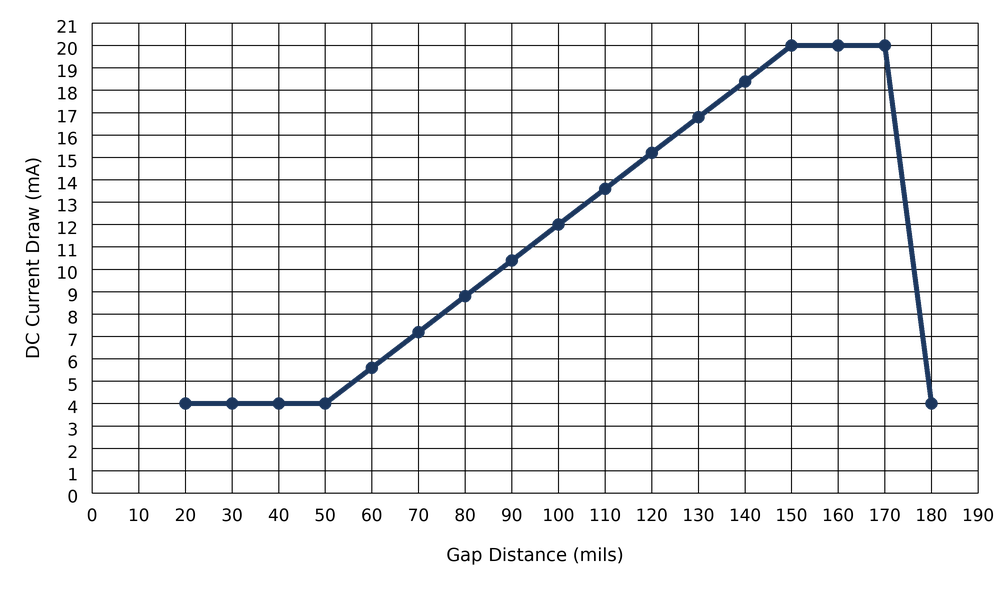
The output is only guaranteed to be linear within this specified ± range. Outside of this range, current signal performance is not defined.
Speed/Phase Analysis Hardware Solutions
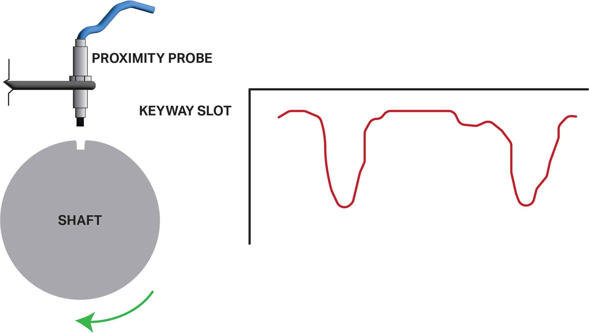
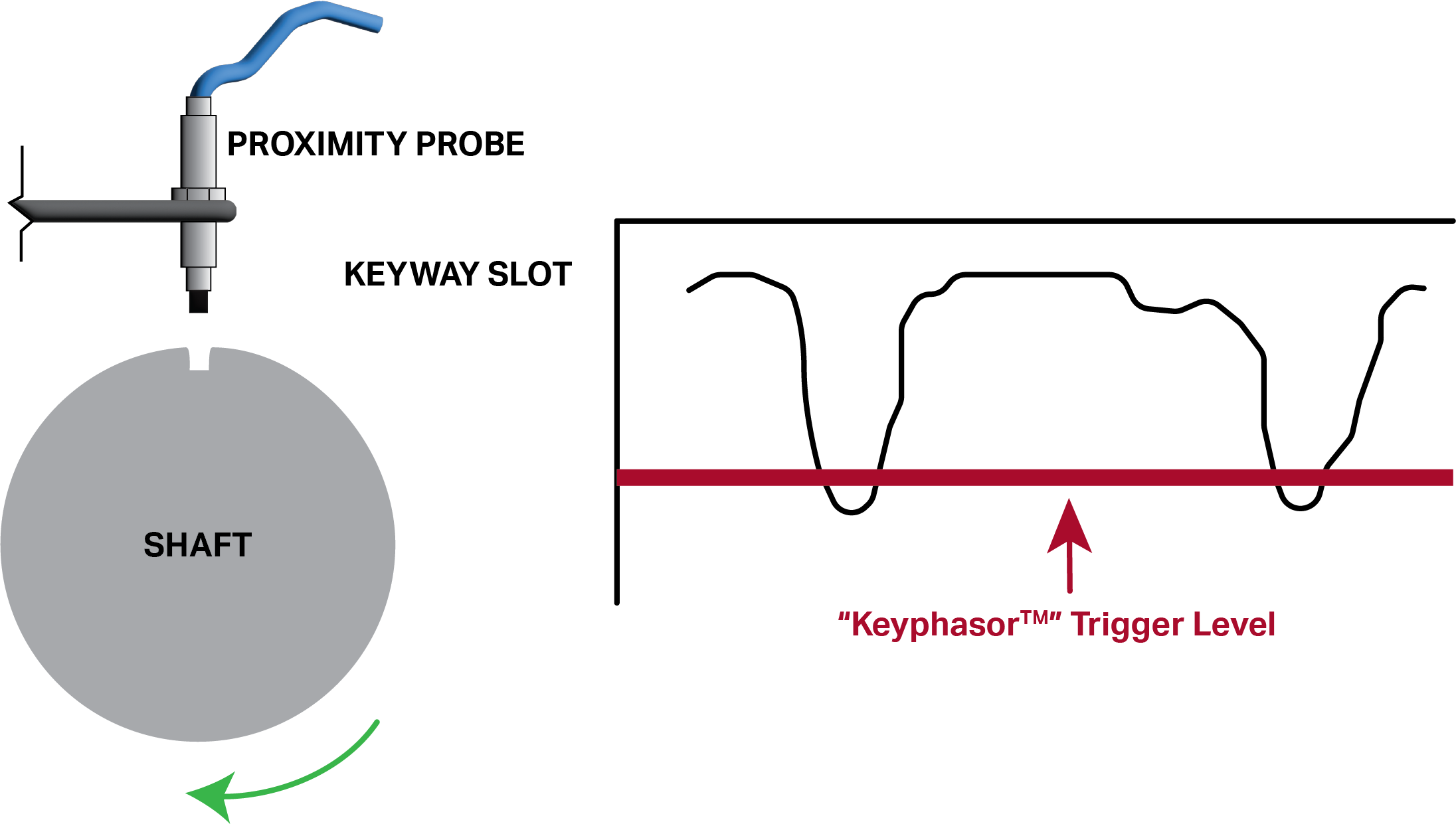
PRO Proximity Probe Systems with Voltage Drivers can be used with Bently Nevada™ 3500 Series modules and external diagnostic equipment to measure the shaft rotative speed and vector parameters such as 1x vibration amplitude and phase when used with a Keyphasor™ module. The input signal range of these keyway modules is +0.8 V to -21.0 V, they are designed to take in dynamic voltage data from standard proximity probes. The real-time displacement measurements from these probes give the modules an indication of when the keyway(s) on the shaft travel in front of the proximity probe.

Dynamic Voltage vs. 4-20 mA Proximity Probe Systems
PRO Line 4-20 mA Current Drivers are great low-cost solutions for applications where it is important to monitor the condition of the machine, but there is no budget or need for a full DAQ rack or MPS (Machine Protection System). 4-20 mA signals are very common process control signals utilized by PLC, DCS, and Control Room Monitors. 4-20 mA signals are very popular because they can travel long distances without degrading, and provide a constant reading that is very easily and cheaply read by a wide variety of commonly utilized equipment. All PRO Line 4-20 mA drivers also feature a fully-isolated BNC on the front of the case, which provides the analyst access to the unfiltered voltage output of the probe.
The two main functions of a proximity probe system are: to identify the (1) vibration and (2) position of a shaft relative to its housing. In order to provide monitoring solutions for these two metrics, CTC offers different 4-20 mA current driver types:
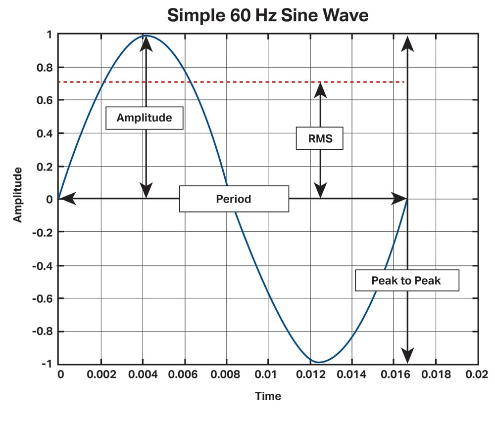
These drivers focus only on the severity of the radial vibration occurring in the shaft measured as the distance between the negative and positive peaks of the vibration sine wave that is generated, also known as peak-to-peak (Pk-Pk) measurement. This is accomplished by only focusing on the AC portion of the original dynamic voltage signal and converting it into a 4-20 mA process signal.
As vibration severity increases, the amplitude of the AC sine wave indicating vibration will increase, thus increasing the distance between the positive and negative peaks in the sine wave. This increase in distance between the peak-to-peak value is represented by an increase in the 4-20 mA output of the probe driver. So, as vibration grows more severe, the AC sine wave portion of the voltage signal will grow larger, which increases the peak-to-peak value and is represented by an increasing 4-20 mA signal. The scaling of this 4-20 mA signal is configurable when ordering this driver type. Below is an example of what peak-to-peak measurement of a waveform looks like:
4-20 mA Axial Probe Driver Series
This driver series only focuses on the DC portion of the original voltage signal and will provide the user data on the position of the shaft while filtering out the AC portion of the signal which indicates vibration. These are primarily used at the end of the shaft or on a shaft collar if there is one available to measure thermal expansion or axial thrust. Often this information is used to trigger alarms and switches to shut down a machine if the shaft moves beyond a designated distance from its original position.
When to Use a Signal Conditioner with a Proximity Probe System
The use of SC300 Series Signal Conditioners is ideal for cases where there are already voltage probes installed (or in stock) and the end-user would like to get a 4-20 mA output, or where specialty configurations are desired. Utilizing an SC300 Series Signal Conditioner will allow for additional configuration options to modify the 4-20 mA signal including selecting a specific frequency range to monitor, additional scaling options, alternative methods of measuring the severity of vibration like Pk-Pk, Peak, RMS, etc., and customized output smoothing features to avoid false alarms and trips. (Note: Drivers and signal conditioners cannot be daisy-chained to their power supply - one 24 V power supply for each unit, two power supplies for each channel of measurement).
Click here to view the SC300 + Proximity Probe Driver Manual