4-20 mA LOOP POWER SENSOR CUSTOMER SUPPORT HUB
Explore tips, tricks, and important information from the experts at CTC to ensure the proper functionality of your CTC 4-20 mA Loop Power Sensors.
Overview
CTC Loop Power Sensors are designed for integration with plant PLCS, SCADA and DCS systems. Every PLC, SCADA, and DCS platform has unique hardware, software, and scaling requirements. If you experience set up or integration issues, please consult the documentation and user manuals provided by your system manufacturer as a first step.
While CTC products are designed to interface with a wide variety of control and monitoring platforms, CTC technical support does not provide troubleshooting or interpretation of third-party system manuals or documentation.
Detailed information regarding CTC Loop Power Sensors, including wiring diagrams, loop resistance calculations, sensor scaling, installation requirements, and product specifications, can be found in the manuals linked below. Please refer to these resources when configuring CTC devices within your control system environment.
Product Manuals
Use the buttons below to view Loop Power Sensor product manuals:
Wiring Quick Reference Guide
Standard 4-20 mA Loop Power Sensor Wiring Diagram (no temperature output):
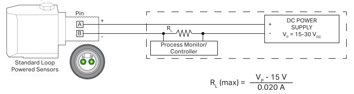
Note: If having issues with the temperature measurement of CTC Dual Output Vibration & Temperature Sensors with 10 mV/C temperature output (LP26*, LP36*, LP56* and LP66* series part numbers), please ensure that your control system can accommodate a voltage temperature output. If not, CTC’s Dual Output Loop Power Vibration with 4-20 mA Temperature Output may be the correct choice for your application (LP57* and LP67* series).
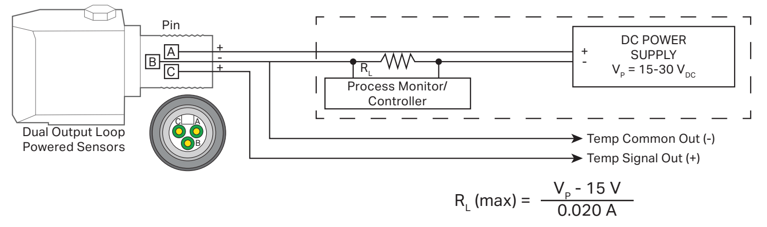
Dual Output 4-20 mA Loop Power Sensor Wiring Diagram:
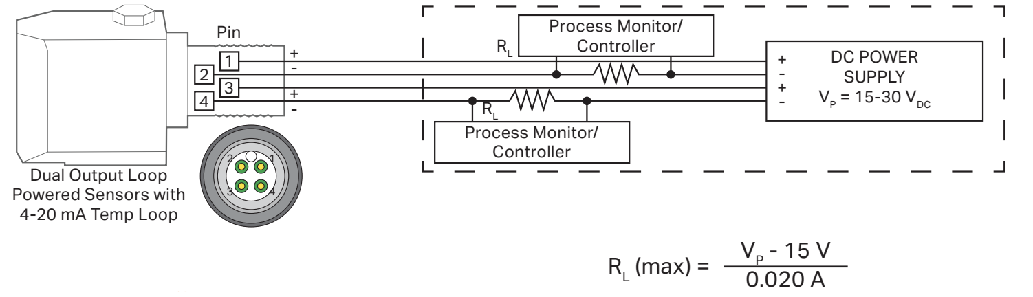
Dual Output 4-20 mA Loop Power Sensor with 4-20 mA Temperature Loop Wiring Diagram:
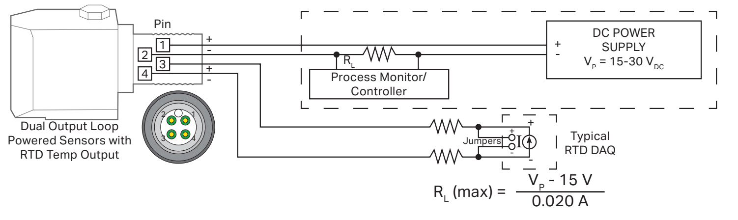
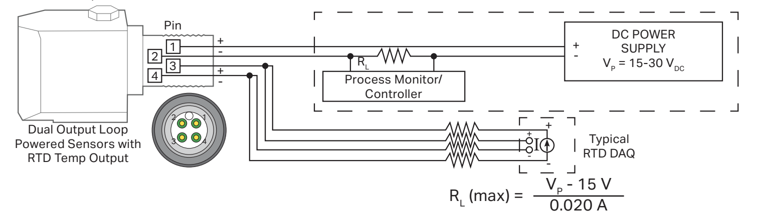
Dual Output 4-20 mA Loop Power Sensor with RTD Temperature Output - 2 Wire System Wiring Diagram:
Dual Output 4-20 mA Loop Power Sensor with RTD Temperature Output - 4 Wire System Wiring Diagram:
Unexpected Output Troubleshooting
If the sensor has been properly integrated with your PLC, DCS, or SCADA system but the output does not match expected vibration or temperature readings, follow the troubleshooting steps below:
Verify Sensor Mounting
Improper mounting can significantly affect measured vibration levels and frequency response.
Check for:
- Loose sensors - CTC recommends a mounting torque of approximately 2 to 5 ft-lb for stud mounted sensors
- Damaged mounting threads
- Uneven or painted mounting surfaces
- Excessive grease, threadlocker, or mounting compounds
Verify Loop Power
Verify the following:
- Power supply voltage meets sensor requirements (15-30 Vdc)
- Polarity is correct
- Loop resistance does not exceed system limitations
- All terminals are properly tightened
- The PLC, DCS, monitor, or data acquisition system channel is enabled
Verify Sensor Scaling
Improper scaling within the monitoring system can cause incorrect readings.
Verify:
- The correct sensor model is configured
- Input scaling matches the sensor output range
- Engineering units are correct
- PLC or DCS calculations are properly configured
Inspect Wiring and Connections
Wiring problems are among the most common causes of loop power sensor issues.
Check for:
- Reversed polarity
- Loose terminals
- Moisture ingress
- Corroded connectors
- Bent, recessed, or contaminated pins
- Excessive cable tension or bends
Swap in a new, unused CTC cable to help rule out cabling as the source of the issue. CTC cables are robust and properly shielded to reduce unwanted noise. While CTC Loop Power Sensors may be used with non-CTC cables, we recommend testing with CTC cables if issues persist.
Sensor Stuck at 4 mA
Possible causes include:
- Incorrect scaling
- No machine vibration in configured frequency band
- Machine vibration too low for proper detection using configured scaling
- (Temp channel) temperature below valid measurement range
- Insufficient power supply
- Internal damage
Sensor Stuck Near 20 mA
Possible causes include:
- Process value exceeding sensor range
- Shorted wiring
- Incorrect scaling
- Excessive vibration or temperature
- Internal damage
Values Greater Than 20 mA
Possible causes include:
- Improper wiring
- Short circuit
- Internal damage
No Output Detected
Check:
- Power supply voltage
- Wiring polarity
- Terminal connections
- Loop continuity
- Input channel configuration