SENSOR INSTALLATION TROUBLESHOOTING GUIDE
If a CTC sensor is producing erroneous field output, use the following steps to troubleshoot the issue:
Verify Sensor Mounting
Improper mounting can significantly affect measured vibration levels and frequency response.
Check for:
- Loose sensors
- CTC recommends a mounting torque of approximately 2 to 5 ft-lb for stud mounted sensors
- For magnetically mounted sensors, verify that the magnet is fully seated against the mounting surface. The magnet should not be able to rock, tilt, or pivot during operation
- CTC recommends a mounting torque of approximately 2 to 5 ft-lb for stud mounted sensors
- Damaged mounting threads
- Uneven or painted mounting surfaces
- Excessive grease, threadlocker, or mounting compounds
Inspect the Cable Installation
Use a CTC TM1223 Test Meter to connect directly to the sensor, or to connect directly to the termination of the cable at the BNC, tinned leads or junction box using one of the supplied test connection cables.
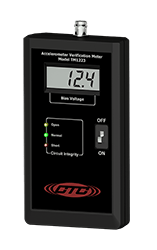
If the meter shows a green light, your cable is in good working condition
If the meter shows a yellow or red light, proceed with the following inspection steps:
Inspect for:
- Cuts or abrasions in the jacket
- Moisture ingress
- Corroded connectors
- Bent, recessed, or contaminated pins
- Excessive cable tension or bends
Swap in a new, unused CTC cable to help rule out cabling as the source of the issue. CTC cables are robust and properly shielded to reduce unwanted noise. While CTC sensors may be used with non-CTC cables, we recommend testing with CTC cables if issues persist.
Check for Grounding and Electrical Noise
Verify:
- Cable shields are terminated according to system requirements
- Junction box connections are secure and wired according to the respective junction box manual
- CTC junction boxes are earth grounded to help reduce electrical noise. If using a non-CTC junction box, consult the manufacturer’s specifications and manual for proper grounding requirements, or consider replacing it with a CTC junction box
- CTC junction boxes are earth grounded to help reduce electrical noise. If using a non-CTC junction box, consult the manufacturer’s specifications and manual for proper grounding requirements, or consider replacing it with a CTC junction box
- No ground loops are present
Verify the Monitoring System Configuration
An incorrectly configured monitoring system can make a properly functioning sensor appear out of specification.
Review:
- Sensor sensitivity settings: ensure that the system is configured for the standard sensitivity of the sensor (i.e. 100 mV/g, 500 mV/g, 1000 mV/g)
- Engineering unit scaling
- Measurement range settings
- IEPE excitation current as it compares to sensor datasheet specifications
- Integrated versus non-integrated sensor configuration: many systems offer integration of acceleration inputs to velocity. Double check all configurations.
- Software conversion factors
- Alarm calculations and data processing settings
When using non-CTC wireless data collection equipment with wired sensors, such as the Erbessd Defiant, verify the equipment is functioning properly. Known issues have been reported with Erbessd Defiant operation, so output should be checked in a controlled environment using a known-good sensor and cable.
Compare Against Another Sensor
When possible:
- Install a known-good sensor in the same location with a known good cable
- Connect the sensor using the same cable and acquisition channel
- Compare vibration data
This method is often the fastest way to determine whether the issue originates with the sensor, cable, or instrumentation.