Pump Monitoring To Extend Mechanical Seal Life
Use this link to download the printer-friendly pdf version
Thank you to our friends at JetTech Mechanical for this article
OVERVIEW
A leaking mechanical seal is often the visible end of a problem that started somewhere else. The seal faces depend on a stable shaft, a suitable fluid film and the right environment in the seal chamber. Cavitation, bearing deterioration, internal contact, misalignment and operation outside the pump’s intended range can disturb those conditions. A new seal installed without correcting the cause may have a short life, whether it is a component seal or a cartridge assembly.
This applies to single and dual seals, pusher and non-pusher designs, and spring or bellows designs. Cartridge versus component describes how the seal is assembled and installed; it does not make the pump immune to hydraulic or mechanical distress. Seal arrangement and support plan still matter: a dual seal’s barrier or buffer pressure, level, temperature and circulation deserve their own checks.
WATCH FOR CONDITIONS THAT SHORTEN SEAL LIFE
Cavitation and Unstable Hydraulics
When liquid vaporizes and bubbles collapse inside a centrifugal pump, the resulting impacts can increase vibration and damage the pump, bearings and seals. Low suction pressure, a restricted strainer, inadequate available NPSH, entrained gas, poor venting and operation outside the specified flow region all deserve investigation. Internal recirculation and other hydraulic instabilities can also create broadband vibration, so a noisy spectrum alone does not prove cavitation. Compare vibration with suction and discharge pressure, flow, speed, temperature, strainer differential pressure and the pump curve before naming the cause.
Bearing Damage and Lubrication Problems
A bearing that develops defects or loses lubrication can allow more shaft motion and heat into the seal environment. Trend high-frequency acceleration or bearing-condition indicators alongside the vibration spectrum and waveform. Investigate changes at the pump bearing housings before the bearing condition progresses into rotor instability or an unplanned seal replacement.
Rubs, Looseness and Alignment-Related Motion
Internal wear-ring or other rotor-to-stator contact, looseness, pipe strain and misalignment can change the way a pump moves. Look for changes in running-speed components, harmonics, sub-synchronous content, impacts, axial vibration and temperature. These are diagnostic clues, not unique signatures. Confirm the cause with operating data, phase or inspection as appropriate. Vibration measured at the bearing housing is not a direct measurement of seal-face contact.
Seal Support Failures
A pump can have acceptable overall vibration and still lose a seal through dry running, flashing in the seal chamber, inadequate flush, contaminated fluid, heat or an incorrect barrier system condition. Monitor leakage and the applicable seal support plan’s pressure, level, flow and temperature. Respond to seal-system alarms on their own merits, even when the vibration trend is quiet.
RECOMMENDED CTC SOLUTIONS FOR SPECIFIC MONITORING NEEDS
Permanent Wired Measurements For Detailed Analysis:
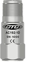
AC192
Compact size, top exit, single axis accelerometer, 100 mV/g, 10% sensitivity tolerance
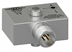
TREA330
Miniature size, side exit, triaxial accelerometer, 100 mV/g, 10% sensitivity tolerance
How To Use:
Collect repeatable acceleration waveforms and spectra at the pump bearing housings. The TREA330 captures three axes at once; configure analyzer bandwidth and mounting for the fault frequencies of interest.
Remote Trend Of Overall Machine Condition:
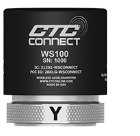
WS100
ConnectSens wireless triaxial overall vibration signal sensor with temperature output
How To Use:
Trend overall vibration on three axes and temperature. Use changes to trigger inspection or a more detailed measurement; overall values alone cannot reliably separate cavitation, bearing damage and rubbing.
Remote Diagnostic Vibration Capture:
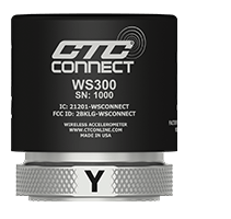
WS300
ConnectSens wireless triaxial dynamic vibration signal sensor with temperature output
How To Use:
Collect three-axis dynamic signals and temperature for waveform and frequency analysis. Select sampling rate, capture length and reading interval for the pump speed and suspected fault, and check the installed configuration against the actual detection requirement.
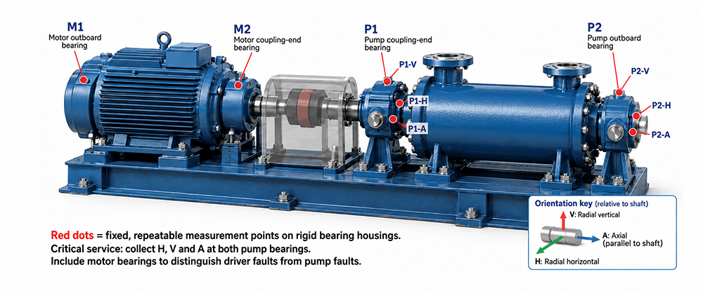
A PRACTICAL PUMP LAYOUT
Place repeatable measurement points on rigid pump bearing housings, starting at the coupling-end and outboard bearings where accessible. Add motor bearing locations to separate driver faults from pump faults. For critical service, use radial horizontal, radial vertical and axial data at both pump bearings; a triaxial sensor simplifies the three directions at a point. Record the precise location and axis orientation. Mount to sound metal with a suitable stud or engineered pad where feasible, and follow the sensor’s mounting instructions. Do not assume a sensor mounted on the seal gland or thin guard represents bearing motion.
TURN DATA INTO EARLY RESPONSE
At commissioning, record a clean baseline with speed, flow, suction and discharge conditions, bearing and seal temperatures, flush or barrier readings, and leakage status. For a VFD pump, compare like operating states or maintain baselines by speed and load. Trend broadband levels and the actual spectra and waveforms where available; use bearing fault frequencies and high-frequency content where the bearing geometry and measurement bandwidth permit it. A sudden broadband increase plus falling suction pressure suggests a hydraulic investigation. A rising bearing-related pattern suggests bearing and lubrication checks. New synchronous or impact behavior calls for checks of alignment, looseness, rub and operating condition.
Set alert and action limits from the pump OEM, site standards and measured baseline. JetTech can initially use a relative increase of 25% as a review trigger and 50% as an action trigger, provided the measurement, speed and operating state are comparable. Those percentages are a site screening approach, not universal safe vibration limits and not a reason to delay action on leakage, rapid change or an OEM alarm. Document the finding, confirm it with process data, correct the cause and verify the new trend after repair.
THE RETURN ON PREVENTING ONE SEAL FAILURE
Based on JetTech’s planning figures, an ANSI pump cartridge seal commonly costs $1,500 to $2,200, while a seal for some API pump applications may cost $10,000 to $20,000. Those are seal purchase costs only. Removal and installation labor, associated bearings or pump repairs, contractor travel, lost production and restart can make the full event substantially more expensive. Actual seal pricing and outage costs vary by equipment and site.
The financial test is straightforward: avoided failure cost = seal purchase + labor + other repair cost + downtime. Compare the value of failures actually avoided over a defined period with the installed monitoring and analysis cost for that same period. For example, avoiding one $2,000 ANSI seal purchase yields $2,000 in direct seal savings before labor or downtime; avoiding one $15,000 API seal purchase yields $15,000 before those additional costs. If an installed monitoring program costs less than the supported avoided cost, it can pay for itself. Record the starting failure rate and the subsequent events so the savings claim reflects evidence, not an assumption that every alarm prevents a seal failure.
A longer-lived seal is the result of a healthier pump system. CTC provides repeatable wired and wireless vibration measurements. JetTech Mechanical combines those measurements with pump field service, laser alignment, vibration analysis and commissioning experience to identify what is changing and why. Watch the bearings and hydraulics, protect the seal support environment, and fix the source of distress before the seal becomes the next failure.
TECHNICAL RESOURCES
CTC
- TREA330 100 mV/g Triaxial Accelerometer
- AC192 100 mV/g Accelerometer
- WS100 ConnectSens™ Wireless Sensor
- WS300 ConnectSens™ Wireless Sensor
Flowserve